

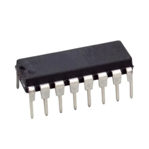
ULN2003 Motor Driver IC (DIP)
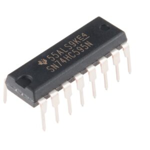
The ULN2003 is a 16-pin IC. It has seven Darlington Pairs inside, where each can drive loads up to 50V and 500mA. For these seven Darlington Pairs we have seven Input and Output Pins. Adding to that we can a ground and Common pin. The ground pin, as usual is grounded and the usage of Common pin is optional. It might be surprising to note that this IC does not have any Vcc (power) pin; this is because the power required for the transistors to work will be drawn from the input pin itself. The below circuit is a simple circuit that can be used to test the working of ULN2003 IC.
Pin Diagram:-

ULN2003 Pin Configuration: –
| Pin Number | Pin Name | Description |
| 1 to 7 | Input 1 to Input 7 | Seven Input pins of Darlington pair, each pin is connected to the base of the transistor and can be triggered by using +5V |
| 8 | Ground | Ground Reference Voltage 0V |
| 9 | COM | Used as test pin or Voltage suppresser pin (optional to use) |
| 10 to 16 | Output 1 to Output 7 | Respective outputs of seven input pins. Each output pin will be connected to ground only when its respective input pin is high(+5V) |
working of ULN2003 IC: –
In the circuit consider the LED to be the loads and the logic pins (blue colour) as the pins connected to the Digital circuit or Microcontroller like Arduino. Notice that the Positive pin of the LED is connected to the positive load voltage and the negative pin is connected to the output pin of the IC. This is because when the input pin of the IC gets high the respective output pin will get connected to ground. So when the negative terminal of the LED is grounded it completes the circuit and thus glows. The loads connected to the output pin can be maximum of 50C and 500mA each. However you can run higher current loads buy combining two or more output pins to gather. For example if you combine three pins you can drive up to (3*500mA) ~1.5A.
The COM pin is connected to ground through a switch, this connection is optional. It can be used a test switch, meaning when this pin is grounded all the output pins will be grounded.
The ULN2803 is a Darlington array IC it can be used to drive Stepper and DC Motors, Relays, Solenoids, and other external circuits operating at high voltages and currents from simple CMOS logic signals from microcontrollers. It has 8 driving channels, each channel can withstand peak currents of 600mA. Suppression diodes are included for back EMF protection while driving inductive loads. The ULN2004 is used in the current version of our 8 Channel Relay Board to drive the onboard relays.
Features
Contains 7 high-voltage and high current Darlington pairs
Each pair is rated for 50V and 500mA
PDIP-16 package
500-mA-Rated Collector Current (Single Output)
High-Voltage Outputs: 50 V
Output Clamp Diodes
Inputs Compatible With Various Types of logic
Relay-Driver
Specification
| IC Name | ULN2003 |
|---|---|
| Package/Case | DIP-16 |
Application
Used to drive high current loads using Digital Circuits
Can be used to drive Stepper motors
High current LED’s can be driven
Relay Driver module (can drive 7 relays)
Logic Buffers in digital electronics
Used as Touch sensor for Arduino
Package Includes
1 x ULN2003 Motor Driver IC (DIP)


Ganesh S. (verified owner) –
good quality
Aayush Kumar (verified owner) –
Good