Arduino Frequency Counter Kit with 16×2 LCD Display
Frequency Counter, as the name indicates, is an electronic device or component, which is used to measure the frequency of a signal. In case of a repetitive electronic signal, a frequency counter measures the number of pulses in that signal.
We generally use an oscilloscope to depict the signal, calculate the time period of the signal and finally convert it to calculate the frequency of the signal. But, oscilloscopes are very expensive and everyone cannot afford it.
Hence, a simple Digital Frequency Counter can be built which might come in handy to measure the frequency of a clock signal, for example.
In this project, an Arduino based Digital Frequency Counter is designed to measure the frequency of an incoming signal.
Circuit Diagram: –
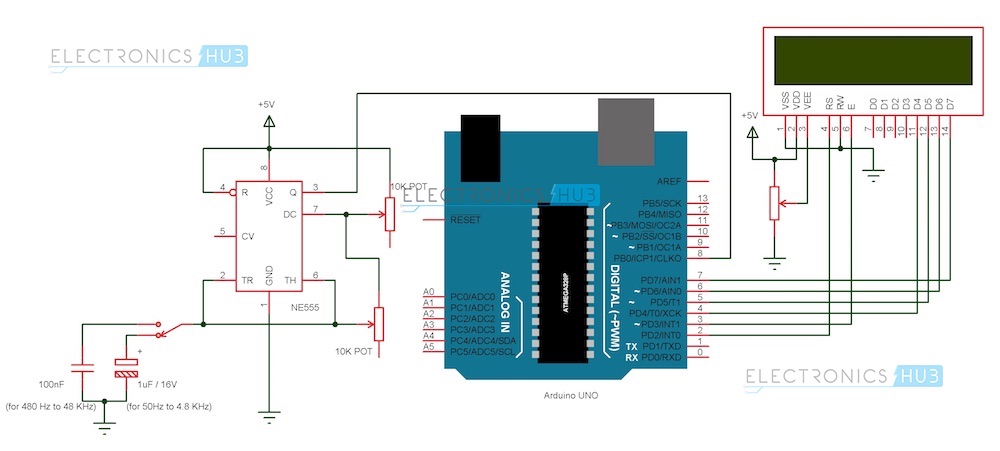
Arduino Frequency Counter Circuit Diagram
Components
Arduino Part
(AI0001) Arduino UNO
(AI0006) 16 X 2 LCD Display
(AI0046) Prototyping Board
(AI0380) Connecting wire
Signal Generator Part
(AI0173) NE555 Timer IC
(AI0174) 10 KΩ Potentiometer x 1
(AI0869) 100 nF Capacitor (Code: 104)
(AI0868) 1 µF / 16V Electrolytic Capacitor
(AI0082) 5V Power Supply (12V is not suitable as it might damage Arduino board).
Circuit Design
The design of the Frequency Counter using Arduino UNO can be divided in to two parts: The Arduino part, where the processing of the signal’s information takes place and the Signal Generator part, where the signal whose frequency to be measured is generated.
Arduino Circuit
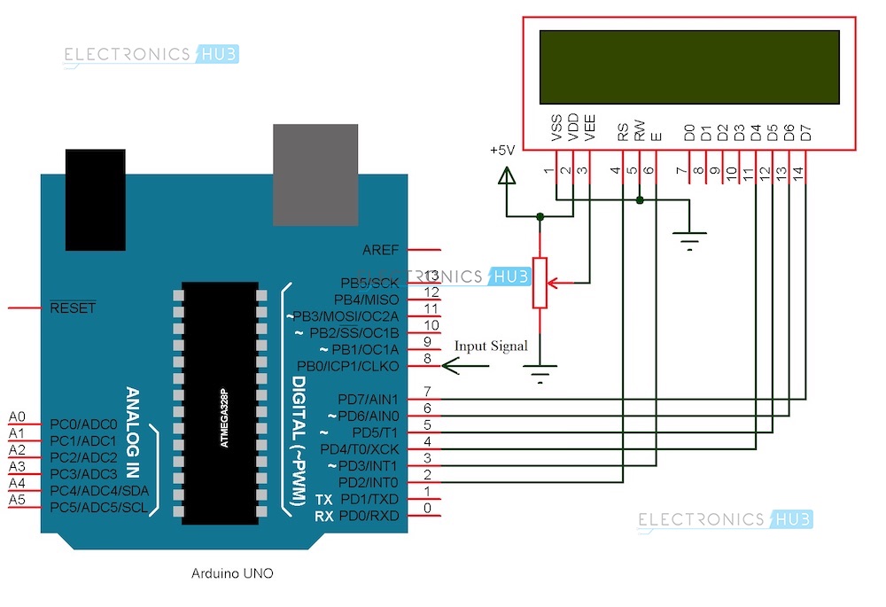
Arduino part of the project consists of Arduino UNO board and a 16 X 2 LCD Display. Pins 1 and 2 of the LCD (Vss and Vdd) are connected to ground and 5V supply respectively. Pin 3 (Vee), which is used to adjust the contrast of the display, is connected a Potentiometer.
Pins 4 and 6 (RS and E) of the LCD are connected to digital I/O Pins 2 and 3 of the Arduino. Pin 5 (RW) of the LCD is connected to ground.
Pins 11 to 14 (D4 to D7) i.e. the data pins of the LCD are connected to the digital I/O pins 4 to 7 of Arduino. Pins 15 and 16 of the LCD are supply pins of the backlight LEDs and are connected to ground and 5V (Pin 16 to 5V through a 1KΩ resistor) respectively.
Features
6 characters wide, 2 rows
White text on the yellow background
Single LED backlight included can be dimmed easily with a resistor or PWM.
Can be fully controlled with only 6 digital lines! (Any analog/digital pins can be used)
Specification
| Model | JHD 16×2 |
|---|---|
| Characters | 16 |
| Character Color | White |
| Backlight | Blue |
| Input Voltage (V) | 5 |
| Length (mm): | 80 |
| Width (mm): | 36 |
| Height (mm): | 14.5 |
| Weight (g): | 30 |
Applications
A simple frequency counter, using simple components is designed that can be used to measure the frequency of a pulse without the need of an oscilloscope.
Multiple ranges of frequencies can be measured by selecting suitable components.
Frequencies of all types of test signals can be calculated by adding a Schmitt Trigger between the generated signal and Arduino.






Reviews
There are no reviews yet.